Schnurzz...
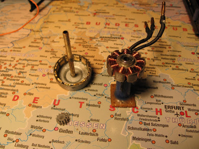
With the rotor removed, note that a 3mm brass tube was used as a shaft. The tube had to be sanded prior to fitting it into the bearings. This shaft is lighter than the original shaft and is directly soldered to the rotor can. When soldering the shaft, care must be taken not to overheat the neodym magnets which are rated to withstand a maximum of 80°C.
The motor base was constructed from a tube cut out of a ball pen's body and a piece of PCB glued together using UHU Endfest 300 super strong epoxy glue. The stator is held in place inside the tube with a couple of drops of 5 minutes epoxy.
Fixing screws are directly dirven into 1.5mm holes in the PCB (same type of screws is used for holding the blade holders together).
The motor was wound with a 0.4mm cooper wire, 14 windings per tooth in a star configuration. This winding works well with a 12 tooth pinion. A plastic pinion runs quieter than the metal one.


No comments:
Post a Comment